We had something of an “ah ha” moment here the other day when the Domestic Steering Committee (a seamstress of note), reminded me that transmitters and snugs are a 3-dimensional design challenge not easily thought of or seen in 2D…
We went back to the snug and transmitter inventory and tried all combinations of transmitters and snugs to see if basically it really is “choose anything you want”. If you’re a Flysky or Futaba user, you might get an “ah ha” moment too.
First up, when I use my Radiomaster Pocket I realise now I’ve always tended to use it without a cover. The transmitter is so ridiculously robust I suppose it felt best to use it in the open air. It was anyway so small it is lost inside a snug.
The second really important thing is that my fabulous Catsails snug is a terrific cover and will basically take anything you want to pop in there with ease – with a Spektrum it can easily accommodate the stubby aerial at any angle you prefer.
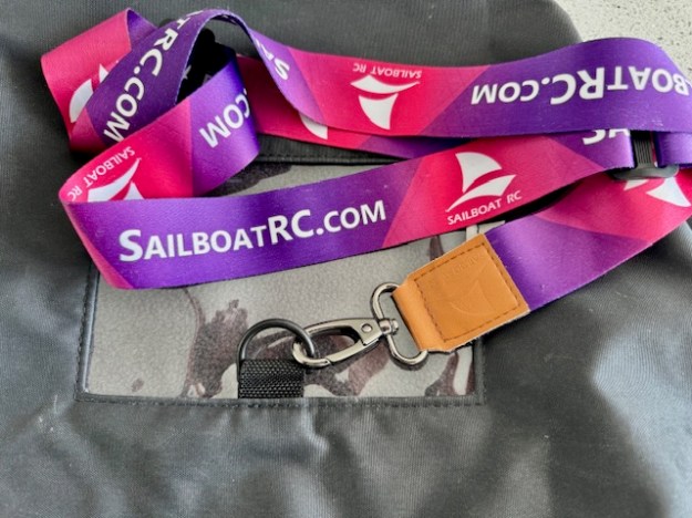
It’ll be interesting to see what SailboatRC come up with in their forthcoming snug design.
What’s the Thing About a 3D Snug Design?
It’s in the implementation….
The Steering Committee’s head seamstress pointed out there are differing approaches here to creating a 3D space for the transmitter. Catsails are basically using what a dressmaker thinks of as “darts”… apparently… there’s a single seam with different material sizes each side of the seam causing a ‘compartment’ effect.
The Rooster…
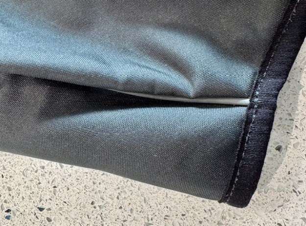
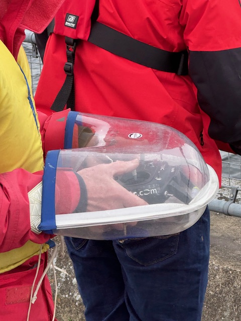
That brings us to the Rooster…. with a different approach to creating a 3D shape based upon multiple seams. They are creating the 3D space more by design with seams along the edges of the 3D space. (see photo at the top of this article)
Can you see there are four seams on the Rooster?? Taped flat on the outside (the Catsails outside seam is “piped”) and also miraculously also flat on the inside for comfort maybe…
In sewing, this is apparently called “flat felling” or “flat locking”. Just so you know…
Given the two people that will have had a big hand (sic) in designing the Rooster snug, it suddenly comes as no surprise to me now that the Rooster 3D space is a really great fit on Flysky and Futaba, like it was designed for them. Like a glove….. My lovely Spektrum is a better fit in the Catsails snug. The antenna stem is something of a compromise inside the Rooster. Enjoy choosing!
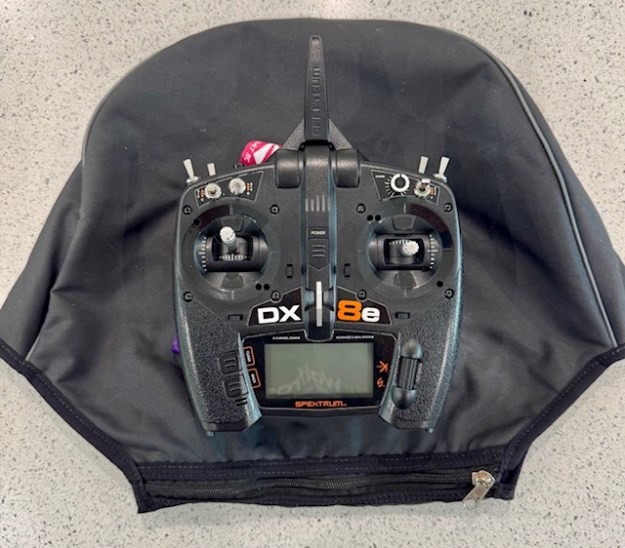
Radio Sailors really can put a lot of thought into transmitter snugs. This brilliant one above, used by our Champion DB, looks like it has an exit for the transmitter aerial… Interesting!!
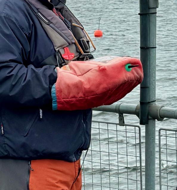
This second example looks totally amazing, but when you realise it is being used by one of our most ‘decorated’ champion radio sailors it gets your mind whirling as to what thinking is being poured in here.(!)
If you’re in a warm climate and don’t use a transmitter snug, consider that one of the most amazing and competitive sailors in UK likes to keep his fingers and switches out of sight, so that competitors can’t get to see what is going on in there. All you hear is a “click-click”. I love it. Fabulous gamesmanship. (See the story of Rodney Pattisson’s Centreboard aileron trim tab on Superdocious… allegedly simply done to distract competition!)
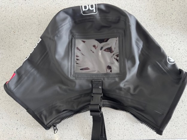
(Note snazzy BG logo sneaking in at the top of the photo to remind you that at least two of the greatest minds in sailing have thought about the design of this snug!)
Do you live somewhere with a climate where the idea of a transmitter snug doesn’t really apply?? Well, here in UK, we use them a lot !!
I saw Rob V with one of the new Rooster Snugs from Steve Cockerill (see above). Very nice it looked too. They make some really nice sailing products at Rooster, so this bodes well !!
There happens to be three different makes of snug in the workshop at the moment. Want to see the differences of design?? Read on….
Since I started radio sailing, I’ve only used a Catsails snug (see above). I borrowed one with a loan boat for a year, then simply stuck with the same. I like it. You’ll see lots of them around – a good well made, well designed, sturdy product.
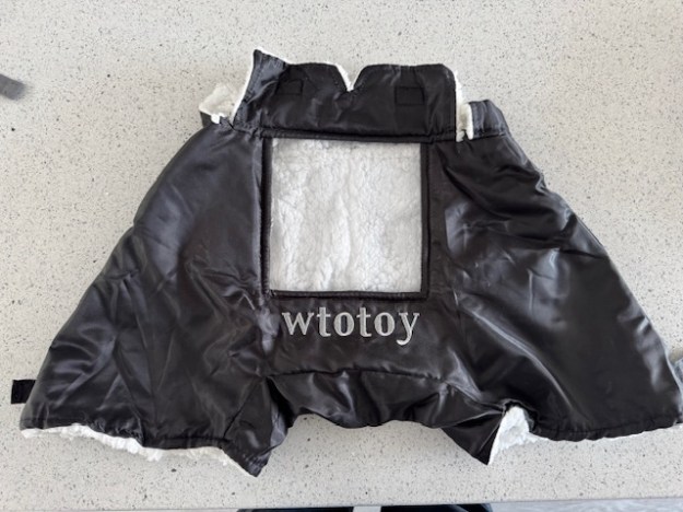
I also have a snug from Wtotoy which I got from SailboatRC with the IOM. I hear that SailboatRC might be about to produce their own design – watch out for that. To be honest, I don’t take to the Wtotoy at all, but it does teach a lot about what sets Catsails and Rooster apart.
When you go to choose your next snug, here are some things to look out for:-
Transmitter Considerations – Access and Security
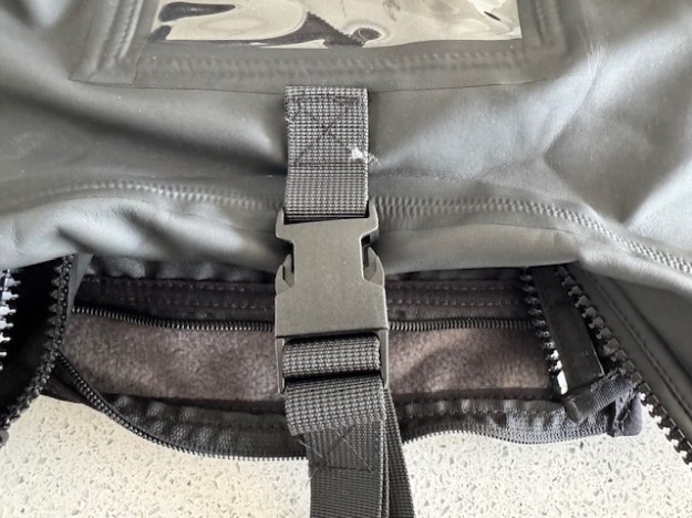
The Rooster and Catsails snugs both have stout strong zippers on the body-side of the snug, compared to a velcro closure away from the body on the Wtotoy snug (see photos above). Thinking through this, my guess is that you would all think the access from body side with a strong zipper was the most secure.
Rooster additionally put this little velcro storage loop inside the snug to secure your transmitter – but to what? Good for Futaba and Flysky transmitters (use the handle) but I’m less sure how to use it best on the Radiomaster Pocket or the Spektrum (slightly more awkward handle to access). Would I forget to do it after a few outings? Better to have it than not though.
Size – Big Hands, Large Transmitters?
(Top photo – Rooster on top of Catsails, bottom photo Rooster on top of Wtotoy)
I thought I had big hands until we ran our item comparing transmitters.
Most probably you’d say that your hands fit all three, but in reality these three feel very different in internal size. I have feeling that the Catsails snug is the most capacious (see photo above), but it might be deceptive. One of them would suit you better, for sure. The Rooster design comes higher up your wrists which is another consideration entirely.
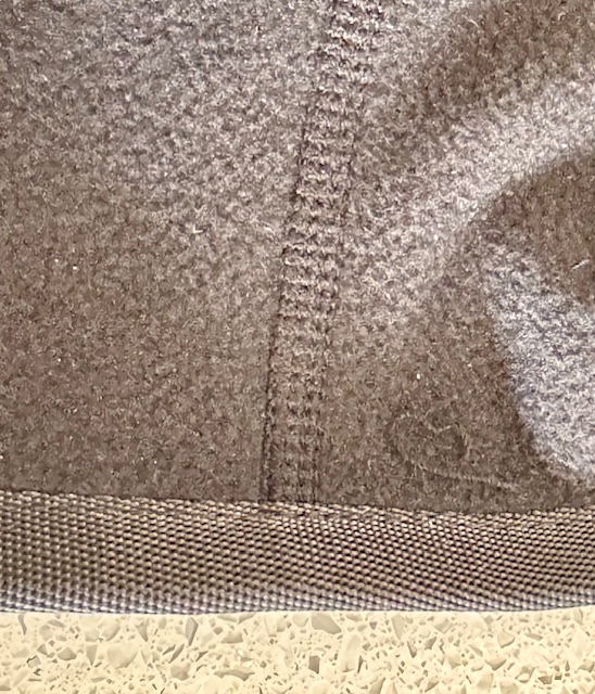
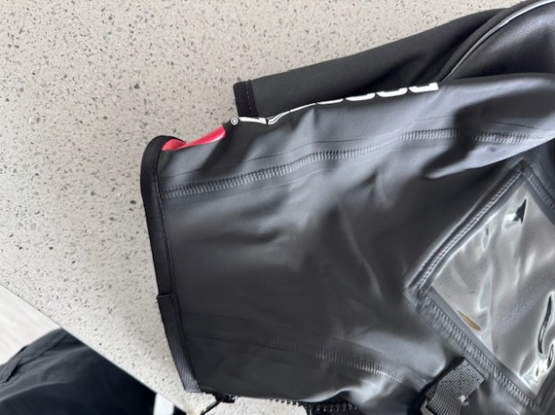
By far the most capacious of the three is the Wtotoy, and the Rooster and Catsails do tend to feel different inside. The Rooster gives a totally different impression as it is designed more to come up your wrists like a pair of gloves. The “sleeve” on the Rooster compared to Catsails is quite pronounced. (see photo below)
If you are a large hands Spektrum user (largest transmitter we have measured) , it’s a double challenge – you are going to want to try both snugs before deciding. Don’t forget your switch clearance! (see our other article)
Let’s start with the Wtotoy and dismiss this. It has no neck strap capability.
The Rooster and Catsails snugs both have an external eye, and the Rooster comes with its own neck strap and quick release buckle.
Both Rooster and Catsails brands have put the securing eye behind the viewing window, so I would guess that the centre of gravity will tilt both away from you if you take your hands off. It’ll vary a lot by transmitter (see our comparison article) weight and centre of balance, but you might want to check this out before you decide.
Weather – Warm or Dry or Both??
In Uk, we would be thinking both about keeping our transmitters dry and perhaps also keeping our hands warm. At our Club, we prefer to sail year round (maximise subscription value!) so both are a prime consideration for us. All three snugs here are made of very waterproof material, so no worries. The Wtotoy additionally has velcro adjusters at the wrists (is this a two person job?) and the Rooster is designed more like a glove to come up the wrist to improve closure.
As regards warmth, you are going to be happy with these, but consider if they would get too hot in summer. I’d guess straight away that the Wtotoy would be warmest and the Catsails the coolest, Rooster in between.
The Wtotoy has a furry lining which is not to my own preference
The Rooster and Catsails snugs both have that clever aqua fleece type of lined material which is robust and (to me) feels great.
I’ll test the Rooster and Catsails next winter to see what their thermal performance is like, but I’d gu ess by design (sleeves effect) the Rooster will be warmest and the Catsails the coolest. What would you prefer?? I confess, I’m not sure yet. When it’s properly cold, do you wear gloves too?
I’ll trial both the Rooster and Catsails snugs over the next year and try and form some conclusions then.
Following our recent article about Receivers in confined “pots” (right angle plugs and in-line plugging issue), I phoned the terrific Inwood Models up in Huntingdon to talk it through.
I called Inwood Models as they were only people I found advertising a Futaba “transmitter-only” price. Lo and behold, the very nice people at Inwood explained they had just sold their last transmitter-only item from stock … but new stock from Futaba is due next week…..With 8 channel receivers included with the product.
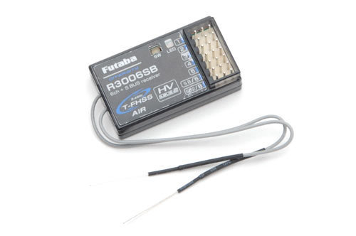
The key thing, as we suggested in our recent article, that Futaba’s distributor is now only packaging the transmitter with a R3008SB 8 channel receiver ….with it’s plugs in-line, not at right angles. Could be an issue for some of us.
The terrific staff at Inwood had clearly already encountered the problem of in-line versus right angle plugging before …. so it’s not just us radio sailors down south! Anyway, they were extremely kind and offered to swap the receiver over when the box from Futaba arrives. Problem solved – thank you Inwood Models.